
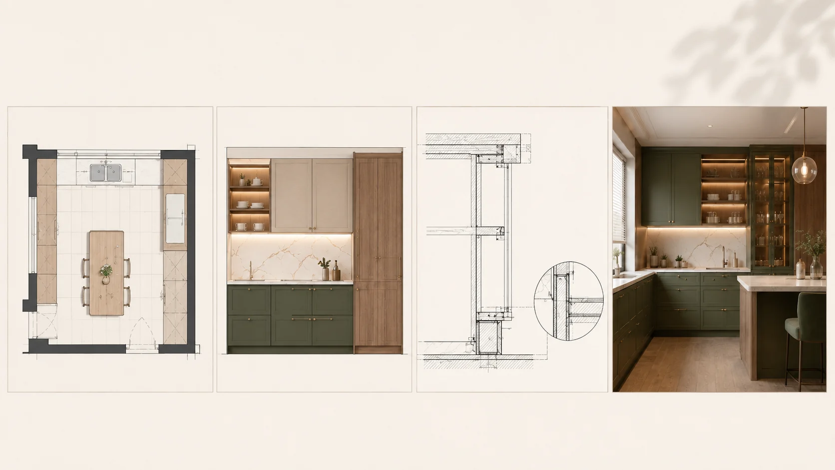
Floor plans, elevations, detail drawings and renderings often appear in the same cabinetry project, but they are not duplicate documents. Each type answers a different question. When one is missing, the project may retain an unresolved gap in space, appearance, construction or expectations.
1. Floor plans: position, scale and circulation
A floor plan looks down on the room. It first answers where the cabinets are located and how they relate to walls, doors, windows, appliances, circulation and other furniture.
- Confirm the location and length of kitchens, wardrobes, vanities and other cabinetry;
- Check whether cabinet depth affects circulation and door opening;
- Review distances between islands, dining tables, beds, sanitary fixtures and appliances;
- Create location references for room numbers, cabinet IDs and BOQ items.
A floor plan is strong at spatial relationships, but it cannot fully define door divisions, front elevations or construction details.
2. Elevations: appearance, divisions and heights
An elevation looks directly at the cabinet front. It answers what the cabinetry will look like and is the main reference for doors, drawers, open niches and appliance spaces.
- Show overall width and height, worktop level and wall-unit level;
- Confirm the proportions of doors, drawers, open shelves, glass fronts and decorative details;
- Define the scope of materials, colours, door profiles and handles;
- Review fillers and closures against tall units, casings, windows, ceilings and walls.
A floor plan can show cabinet location, but not the accurate front divisions or door quantities.
3. Detail drawings: construction, connections and installation
A detail drawing enlarges a special location. It explains structural relationships that are too small in an elevation and too technical for a rendering. These details are essential for workmanship feasibility and installation quality.
| Typical detail | Information to clarify |
|---|---|
| Cabinet-to-wall closure | Fillers, exposed panels, tolerances and treatment of uneven walls |
| Worktop and cabinet | Thickness, drop edge, upstand, support, joints and cut-outs |
| Corners and unusual shapes | Door swing, internal space, connections and installation sequence |
| Lighting and power | Channel size, aluminium profile, wiring, drivers and maintenance access |
| Ceiling and tall units | Top closures, access panels, tolerances and installation order |
A project may not need many detail drawings, but missing details at critical locations make quotation difficult and force installers to improvise.
4. Renderings: visual direction and shared expectations
Renderings are the most intuitive documents for confirming colour combinations, atmosphere, material appearance and overall proportions. They help clients, designers and factories share one visual direction.
- Confirm overall style, colours and material combinations;
- Review the visual effect of lighting, glass, metal and open shelving;
- Compare options and reduce misunderstanding from written descriptions;
- Communicate design intent without replacing technical dimensions and construction drawings.
A rendering answers “how it should look.” Technical drawings answer “how it will be made.” They should correspond, but they cannot replace each other.
5. How the four drawing types work together
| Project stage | Main documents | What is reviewed |
|---|---|---|
| Concept approval | Floor plan and rendering | Layout, circulation, style and overall direction |
| Quotation preparation | Floor plan, elevations and BOQ | Product scope, dimensions, quantities, materials and hardware |
| Detailing | Elevations, sections and detail drawings | Divisions, construction, fillers, connections and appliance fit |
| Production and installation | Approved production drawings, details and installation drawings | Final dimensions, IDs, workmanship and site sequence |
6. What takes priority when drawings conflict?
Conflicts should not be resolved by personal judgement on site. First check revision numbers and issue dates, then obtain confirmation from the project lead. Renderings normally remain a visual reference, while final dimensions and production methods should follow the approved technical drawings, detail notes and BOQ.
A complete drawing set does not repeat the same information four times. It explains the project from four directions—space, appearance, construction and visual intent—so quotation, production and installation can use consistent information.
 Quotation File Checklist
 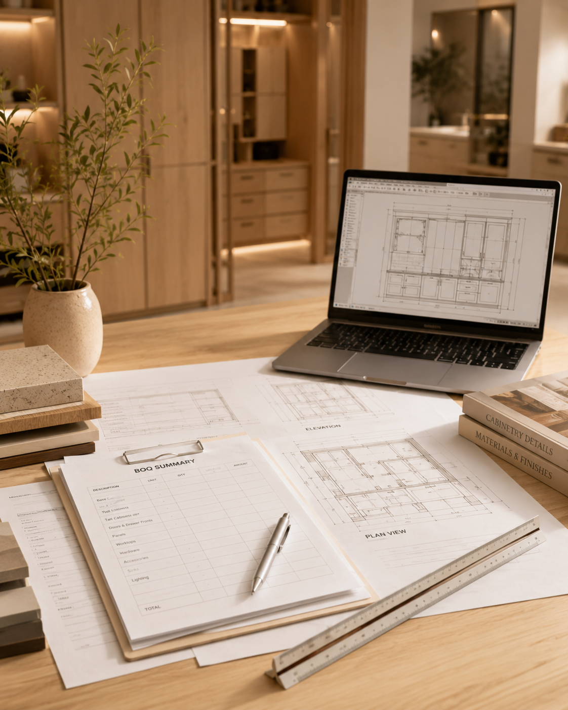 Drawing & BOQ Preparation
  Drawing Preparation Guide